THERMAL POWER PLANT
Clean energy
from scrap recycling
THERMAL POWER PLANT
Clean energy
from scrap recycling
The thermal power plant co-generates electrical and thermal energy using solid biomass, mainly from renewable sources. The thermal energy makes the Faenza plant completely self-sufficient, while the electrical energy not only covers all its needs but is also fed into the national grid for the benefit of the public.
Thermal power plant information
| Parameter | Average value |
|---|---|
| Number of combustion lines | 1 |
| Combustion technology | air-cooled moving grate furnace |
| Rated electrical power | 13,7 MW |
| Hours of operation | 7.800 h/year |
| Combustibili solidi | Solid fuels spent marc, ligno-cellulosic scraps, secondary solid fuels, and coarse fraction |
Environmental compatibility in compliance with current legislation (Italian Legislative Decree no. 152/06)
Plant operating cycle
Trucks delivering solid fuels are weighed at the entrance to the plant, where there are two cell weighbridges, one for incoming vehicles and the other for outgoing vehicles. The trucks then proceed to the unloading area for the type of fuel being delivered, where an operator checks that the material meets the required specifications.
- Fuel handling
This is carried out with mechanical shovels to ensure standard mix preparation and loading of the feed system.
- Combustion chamber fuel feed system
The loading inlet consists of a sheet metal hopper fed directly from the conveyor belt via a modulating fuel metering system. The hopper is connected to the furnace via the feed chute that conveys the fuel into the combustion chamber. The ducts are water-cooled. A hydraulically operated guillotine damper is located between the bottom of the hopper and the inlet of the feed chute, protecting the feed chute from flames rising from the furnace.
The fuels are pushed into the combustion chamber by a hydraulically operated piston feeder, the speed of which varies according to the characteristics of the fuel to ensure uniform distribution.
The furnace is of the air-cooled moving grate type. The reciprocating motion of the grate steps moves the biomass forward into the combustion chamber while mixing it. Mixing the biomass aids combustion by reducing the presence of unburned material in the final ash. The air required for the combustion process is introduced into the chamber either through the grate (primary air) or through openings in the side walls (secondary air). In addition, to increase energy efficiency, the primary air is preheated by heat exchangers using the steam produced by the boiler before entering the combustion chamber.
To ensure complete combustion, the residues are sent to the post-combustion chamber, the dimensions of which ensure that the flue gases remain at a temperature of more than 850°C for at least 2 seconds in order to prevent the formation of dioxins. This temperature is maintained, even in the presence of low calorific biomass, by two natural gas-fired auxiliary burners that are automatically activated depending on the flue gas temperature. The first stage of flue gas treatment is also carried out in the post-combustion chamber by injecting an ammonia solution to reduce nitrogen oxides (Non-Selective Catalytic Reduction – NSCR). When the combustion residue reaches the end of the grate, it falls into a water tank to ensure that it is completely extinguished. It is then transferred to the storage pit by removal and transport systems.
The combustion gases, after passing through the post-combustion chamber, enter a recovery boiler (steam generator) which produces 50 t/h of superheated steam at a pressure of 50 bar and a temperature of 480 °C via a condensation turbine. These gases then enter the boiler at around 950-1000°C and leave it at around 180°C to be treated.
- Combustion chamber nitrogen oxide reduction system (NSCR)
- Quenching tower
- Chemical treatment tower (Lime/Bicarbonate and activated charcoal)
- Bag filter
- Nitrogen oxide reduction system (Catalytic DeNox)
- Final wet guard treatment
The power generation system is designed for the cogeneration of electrical and thermal energy. The turbo-alternator used in the plant is a two-stage condensing turbine with low-pressure steam tapping at the first stage outlet. The tapped steam (at a pressure of 5 bar absolute and a temperature of 175°C) is collected by the low-pressure manifold and then sent to the thermal degasser, to the steam consumers in the plant, and to a district heating network serving the Caviro Extra plant and industrial, commercial, and domestic users in the surrounding area.
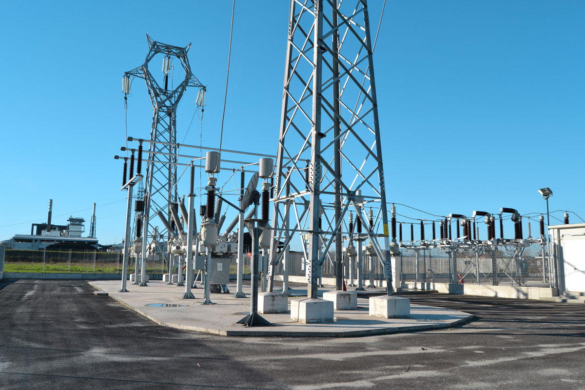
The energy produced by the alternator, which is coupled to the turbine shaft, is used to meet the needs of Enomondo’s facilities. The excess energy, approximately 76% of the energy produced, is partly sold to the Caviro Extra plant and the rest to the national grid. The steam discharged from the second stage of the turbine (at a pressure of 0.12 bar absolute and a temperature of 49.4 °C) is sent via a 1.200 mm diameter supply pipe to an air condensation system located above the turbine room.


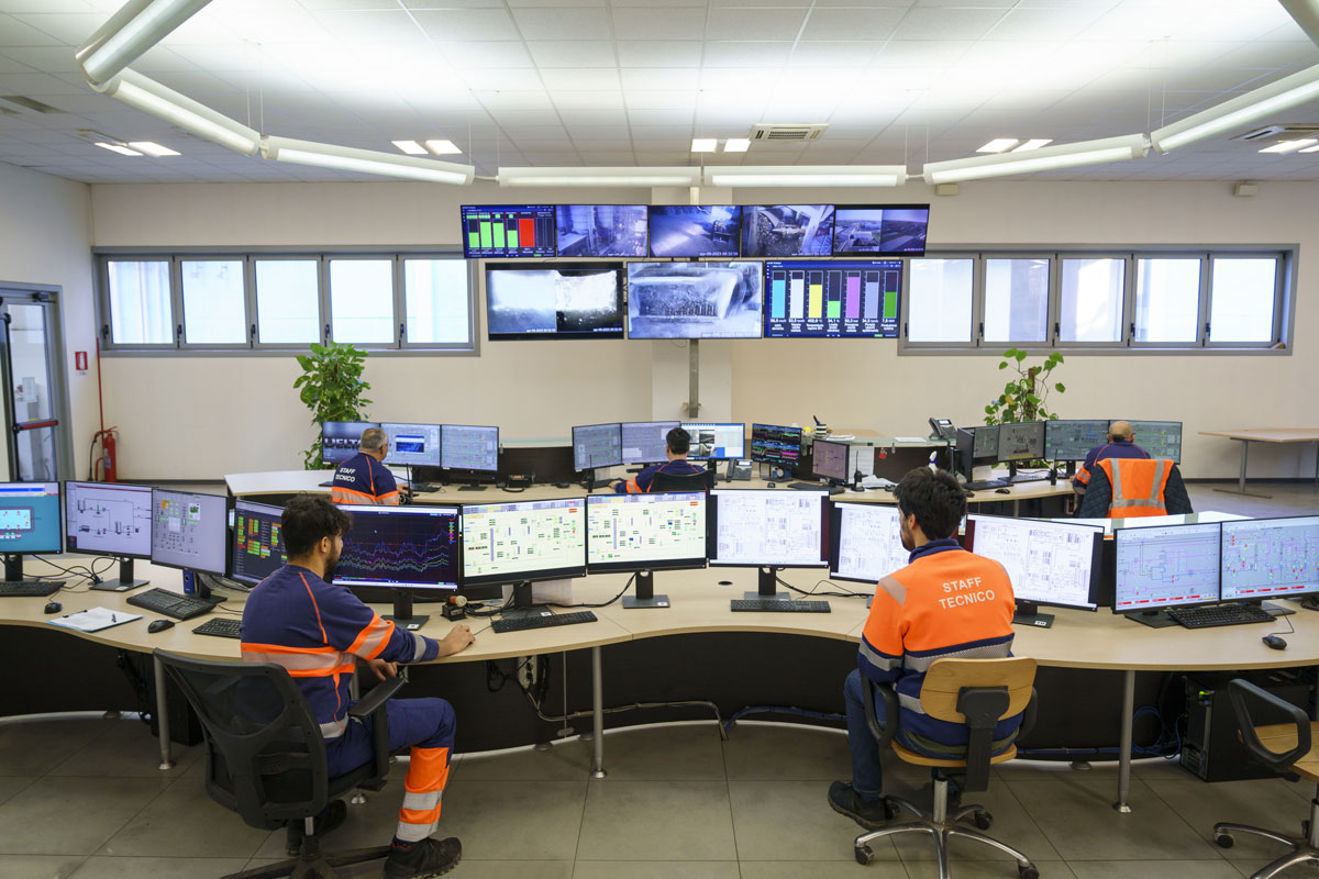
Emissions monitoring
Combustion gases are discharged through a 50-metre high stack. The emission point is monitored in accordance with the relevant regulations. The plant is equipped with a Continuous Emission Monitoring System (CEMS), which uses automatic analysers operating 24 hours a day to continuously monitor the quality of the emissions into the atmosphere.
A suitably heated sampling probe repeatedly conveys a gas sample from the plant stack to the analysis room. The sample enters the interferometric infrared spectrometer (FTIR) analyser, which continuously measures the absorption spectra of the compounds of interest. Using mathematical processing, the spectra present are compared with typical spectra of the substances in question. From this comparison, the concentrations of the elements and compounds of interest can be determined. In addition to the FTIR system, other analysers and instrumentation are used to complete the flue gas analysis by determining other parameters such as dust, organic compounds, oxygen, temperature, flow rate, and pressure.
A data acquisition system provides the values obtained by processing the half-hourly and daily averages of the concentrations, which are then compared with the maximum permissible limits set by the control authorities.